Arduino and Flash an LED Tutorial - and a Capacitor
What You Will Find in This Tutorial:
I worked on only giving the necessary simple things in the Bare Bones section. It will allow you to learn how to connect the circuit from looking at the schematic. You will also see the sketch (aka: program). There is also a picture of an Arduino board and the major parts are pointed out.
In the Extras section you see a schematic using two resistors, the LED and an electrolytic capacitor (be careful with electrolytics!) to fade in and out the LED. There are also some pictures of traces of the signals as applied to the circuits so you can see what is happening that way. There is some explanation in this section. It turned out to be a good refresher on using an oscilloscope and analyzing how resistors, capacitors, and one of the basic ideas of how Arduino GPIO pins work.
THE TUTORIAL
Make sure to use equations necessary as well as schematics. Graphs can also be used.
Materials Needed:
1) 2 LED’s of any colour
2) 3 current limiting resistors, 1kohms.
3) One 50kohm potentiometer
4) 1 x 1000 uF electrolytic capacitor
5) Any kind of Arduino board
6) Jumper wires
Optional:
- Oscilloscope
- Digital Multi-meter (DMM)
- Jumper wires with alligator clip ends
BARE BONES:
This section gives you just the necessary information to do the tutorial. It does not give a lot of background information. If you do not understand something, take the time to read the whole tutorial, at least to the end of the Bare Bones section. There might also be some information useful to you at the end of the tutorial where I elaborate a little on some of the tutorial - such as looking for specification sheets.
Step 1:
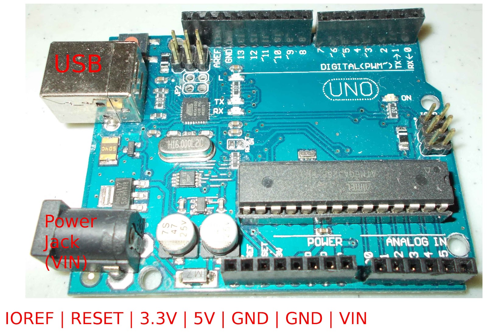
The basic parts of an Arduino board:
>USB jack - connects the Arduino and the computer
>Labelled in red in the picture below
>The power section pins
>Labelled in red below - take note that the Arduino designers have left one pin in this section to be used for a purpose yet to be determined. That is the pin on the left.
>The Tx (labelled TX->1) and Rx (labelled RX<-0) pins - On the upper side of the board in the picture
>labelled in white.
>The rest of the digital IO pins including Pin 13
>also labelled in white
>The analog input pins
>labelled in white - beside the power section pins
>The Power Jack
>labelled in red and located below the USB Jack. It is used when making projects that require more current than the USB port can safely provide.
Step 2:
The most important equation used in electronics: V = IR
This is also one form of Ohm’s Law in case you want to look that up later.
Most LED’s have a forward voltage of Vf = 1.7V to 2.5V.
Use the concept of voltage drops as shown in the schematic below:
Here are the voltage drops in the circuit above:
VTotal = 5V
VLED = 1.8V AKA: Vf of an LED
VR = VTotal - VLED = 5V - 1.8V = 3.2V
Now, what do we do with that information - determine the value of current limiting resistor to use.
VR = IR
We have VR. We need to find R. How do we find I? Looking at a specification sheet will tell you that typical If for a red LED is 20mA. See more on reading specification sheets at the end of the tutorial.
Solve for R:
R = VR / If = 3.2V / 20mA = 160 ohms.
In practice, most LED’s will work fine with R = 100 ohms to 1kohms. Anything less than 100 ohms and you really need to be sure of your math so you do not burn out the LED and possibly the GPIO pin on your device.
Step 3:
Build the circuit. Use the schematic above for reference. The picture below can also be used for reference. Take note of the labels of the rows and columns.
Choose a resistor of appropriate value between 100 ohms to 1 kohms.
Take a jumper wire and plug it into Pin 2 along the Digital side of the Arduino. Pin 2 is beside digital Pin 1, which is marked on the Arduino as TX->1.
Plug the other end of the jumper wire into a column on the breadboard.
Take the chosen resistor and plug on end of it into the same column as the jumper wire on the breadboard.
Plug the other end of the resistor into another column in the breadboard.
Take the anode of the LED and plug it into the same column as the free end of the resistor.
Plug the other end of the LED, the cathode, into another free column of the breadboard. HINT: LED’s come with the anode longer than the cathode.
Plug in a jumper wire into the same column as the cathode of the LED.
Plug in the free end of the jumper into a GND pin on the Arduino.
Step 4:
Write your sketch (aka: program) in the Arduino IDE. Below is an example.
// program: blink_led.ino
// The double forward slashes indicate comments. This type of line is used to explain
// things in a program. This helps when you are not familiar with things and need a
// reminder. It is also used to help others understand what your code does.
/* Comments can also be preceded with the first two characters of this line and
succeeded by the last two characters. This allows comments to span more than one
line in a sketch. */
int led = 2;
void setup()
{
pinMode(led, OUTPUT);
}
void loop()
{
// turn LED on
digitalWrite(led, HIGH);
delay(1000); // 1000 is 1000 milliseconds, 500 is 500 milliseconds
// turn LED off
digitalWrite(led, LOW);
delay(500);
}
This is the first sketch that everybody uses to check to see if their Arduino is working. Once your sketch is typed in, save it using the name provided at the top, file extension is not included as the Arduino IDE will add it.
While writing the program, I mistyped pinMode() as pinmode(). It did not compile correctly and gave me an error message in the Console. Take the time to read the error messages that appear there. While you might not understand them at first, you will become familiar with them and they will help you debug your program.
Try mistyping the same command in your program. Compile it or try to upload it and see the error message provided.
Step 5:
Get into better programming right away: Setting up the serial terminal for manual debugging.
At some point, quite possibly even during typing in this sketch, you made a mistake and the program did not compile properly, did not upload, or did not operate as expected.
If it is one of the the first two problems mentioned, then you need to check the Console for error messages. The Console is the black area at the bottom of the IDE. You can copy them and paste them into a search engine in your web browser to find out what they mean. Read them first to see if you can decipher what they mean.
Here is a link to the Processing IDE parts (I could not find one for Arduino. The Arduino IDE is based on the Processing IDE.):
In the setup() function, type the following to initiate the Serial Terminal.
Serial.begin(9600);
In the loop function type the following line after the part that turn on the LED:
Serial.write(“ON”);
After the part that turns the LED off, type:
Serial.write(“OFF”);
Save your sketch under a new name such as:
blink_led_serial
Remember that you do not have to type in the .ino file extension during the Save process.
Upload the program to your Arduino. Click on the Serial Terminal icon in the upper right side of the IDE. It looks like a little magnifying glass.
You should see a series of ON/OFF messages in the window that pops up. The messages will appear almost at the same time that the LED turns on and off.
This becomes useful as you learn more about programming and your sketch uploads but does not operate the way expected. You can place Serial.write(); statements wherever needed in the sketch so you can see the values of variables as they are used. You can become quite inventive in your debugging, making use of all kinds of statements and functions to help with your debugging.
An example would be to include an extra delay(); statement in your sketch so you can have the time to examine the variable printed in the Serial Terminal. The Serial Terminal also will accept input to be transmitted to the Arduino so be sure to look that up. That can also be used as a trigger in your sketches.
Since we are talking about the Serial Terminal, you should know that GPIO pins 0 and 1 are used to Receive (Rx) and Transmit (Tx) (see picture of Arduino above for labelling) . You should avoid connecting things to these pins as they perform those special functions. Yes, learn a little more about them and you can do different things, but I do not have that experience.
EXTRAS:
The common point referenced in schematics is more often than not called ground. However, do a little reading and you will find out that ground should be used when referring a common connection that is made to a wire or some other connection that goes to ground, actual earth.
Ground and common are parts of the same topic that should be investigated. With many circuits, there is no real ground, just a common. However, that statement, or anything else in this post are the final word on the topic. You should do some reading on the subject.
Using Capacitors to Fade Out an LED:
When first using electrolytic capacitors you should wear safety glasses. If plugged in the wrong way they can pop and expel harmful substances. The negative side of an electrolytic capacitor is marked with a line as seen in the picture in Step 3).
On to using capacitors in a way that allows the LED to fade out instead of blinking out.
A capacitor holds an electrical charge. That charge can be positive or negative. When placed the wrong way in a circuit, they can explode and expel harmful materials that can cause a chemical burn. That is a topic you can research on your own.
Here is a simplified circuit that can be used as an experiment if you want to work out the time it takes to charge a capacitor. Luckily, the circuit used to fade an LED out with an Arduino is not a whole lot more complicated.
Below is an equation used to determine how long it will take to charge capacitor, C.You will want to reference the 2nd equation. The first equation is there if you want to use it and look at a graph of the instantaneous voltage level plotted against time. The value  can then be thought of as chunks of time it takes to charge the capacitor. Do a websearch and find out how that looks.
the final voltage will be 5V.
So the equation can also be written as:
This is a more convenient equation to use to figure out how long a capacitor to charge given a known capacitance and resistance in the circuit.
Let’s use something simple like:
R = 1k
C = 1 F
F
Sorry for the units being all over the place. Google Blog does not like it.
Take 6RC = 6(1ms) = 6ms
6ms is not very long.
The plot above is a rough approximation of the instantaneous voltage,  . What it does show is that it takes about 6 units of
  to fully charge the capacitor. The plot is an approximation and what is not represented is that the charge will never actually reach
  . 6 is 6ms, as mentioned above. Using a capacitor with capacitance of 1uF will allow the LED to fade in and fade out, just not at a speed that the human brain can detect.
Step 6:
To understand how fast a millisecond is, you can do an experiment with the materials you have on hand and the circuit you have already built. Using the sketch, take out the following commands in the sketch:
Serial.begin(9600); and
Serial.write(led, HIGH); and
Serial.write(led, LOW);
Removing those statements will speed up the program for what you are about to do. Serial communications take time and to keep the write statements in the program while changing HIGH and LOW states of the LED would slow things down too much. It would not really be useful for this part anyway.
At the moment, your sketch is a very simple program that turns an LED on and off at the rate of 2 seconds on and 1 second off. You are going to shorten the on and off cycles down to 10’s of milliseconds or less and see at what point you can tell that the LED is no longer blinking.
It should be around 20ms or less.
Now, you can understand why you need longer times to let the capacitor charge and discharge. You can do two things to allow the time unit of to be longer. You can change the resistance and you can change the capacitance. To change the resistance it would be useful to use a potentiometer so you can change the resistance value. If you do use a potentiometer, connect it as a rheostat and not as a voltage divider.
Step 7:
To change the capacitance, you will have to go up to about 1000uF to make a nice decent fade-in and fade-out. You will have to use an electrolytic capacitor to get up to 1000uF so be careful when connecting it. Putting an electrolytic capacitor in backwards can cause it to pop, even expel the harmful material inside. Take care to use safety glasses.
Using the same resistance and a 1000uF capacitor will increase by 1000. Now:
New Circuit and the First Circuit:
FIRST CIRCUIT:
NEW CIRCUIT:
There are two important things when dealing with capacitors:
1) Whether or not it is electrolytic and
2) The voltage rating.
- Do not put in an electrolytic capacitor in backwards.
- Use a capacitor with the proper voltage rating. If the voltage rating is too low, the capacitor’s dielectric will not be able to withstand the voltage differential between the polarities which it handles.
Using both circuits will make it easier to see how much the LED with the capacitor fades in and out.
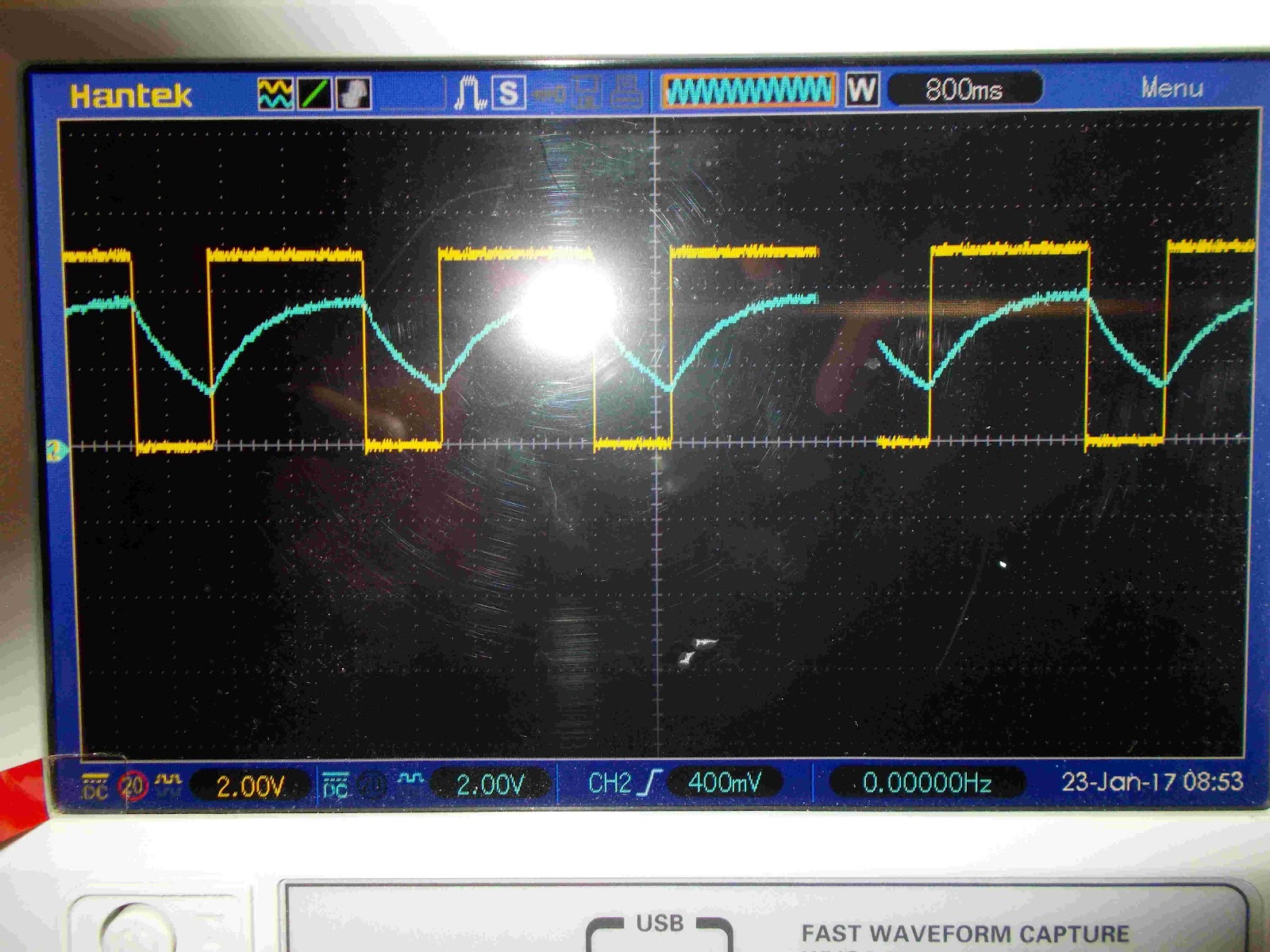
Below are two photos of the oscilloscope probes attached to circuits. The yellow trace is the signal from the probe attached at a point between Pin 3 on the Arduino and a 1kohm resistor. The blue trace is a probe attached to the circuit attached to Pin 2 of the circuit. The difference between the two traces is that the circuit attached to Pin 2 on the Arduino uses the circuit with the 1000uF capacitor.
The two traces show how the capacitor charges and discharges to allow the LED to fade in and fade out. The charging/discharging cycles are shown clearly.
2 Seconds On, 1 Second Off:
2 Seconds On, 1 Second Off:
6 Seconds On, 6 Seconds Off:

If your LED with the capacitor is not fading in and out nicely, try using longer delay times. Remember that a command:
delay(1000);
Means the program will allow the HIGH or LOW state to happen for 1000ms.
delay(2000);
Allows the program to have HIGH or LOW for 2000ms = 2 seconds.
Another useful bit of information is that when the capacitor discharges, the current actually does flow in the opposite direction after the LED turns off completely. So the current discharges from the capacitor and after the forward voltage drops below the forward voltage of the LED, the capacitor is forced to disharged the rest of its current back into the output pin. This is possible and used in some cases where somebody might want a lack of voltage to make a transistor turn on. Do a websearch on the topic.
Math shows that the voltage drops across the resistors should be 1.65V when the forward voltage is 1.7V. Measurements show forward voltage to be 2.6V.
Using the forward voltage to be 2.6V gives the following:
VTotal = VF + VRTotal
VRTotal = VTotal - VF
VRTotal = 5V - 2.6V = 2.4V
ITotal = VRTotal / RTotal = 2.4V / 2kohms = 1.20mA
VR1 = ITotal x R1 = 1.20mA x 1kohm = 1.2V
This works out to be fairly close to what is measured in the circuit. Each resistor had a voltage drop of about 1.1V.
Step 8:
TRY THIS CIRCUIT:
The interesting thing about the circuit immediately above is that the LED does not fade out as with the previous circuit. It looks like the LED turns off when there is not the necessary forward voltage.
NOTE: Fading an LED in and out of the On and Off states might not be the best choice for such a task. It is probably done more easily using the Arduino Sketchbook example called Fade. Fade can be found in the IDE Examples section under 01. Basics. The Fade sketch uses a PWM ability. PWM stands for Pulse Width Modulation. If you look at the two pictures of the oscilloscope traces above, you will see that the yellow trace is a square wave. PWM uses a square wave and changes the amount of time in the HIGH or On position to change the brightness of the LED. An explanation is found on the Arduino side here:
https://www.arduino.cc/en/Reference/AnalogWrite
While the capacitor might not be the best use of components, it does cut down on code, but probably not a whole lot. However, if you have taken the time to work through this part of the tutorial, now you have a good idea of how capacitors work!NOTE: Fading an LED in and out of the On and Off states might not be the best choice for such a task. It is probably done more easily using the Arduino Sketchbook example called Fade. Fade can be found in the IDE Examples section under 01. Basics. The Fade sketch uses a PWM ability. PWM stands for Pulse Width Modulation. If you look at the two pictures of the oscilloscope traces above, you will see that the yellow trace is a square wave. PWM uses a square wave and changes the amount of time in the HIGH or On position to change the brightness of the LED. An explanation is found on the Arduino side here:
https://www.arduino.cc/en/Reference/AnalogWrite
RESISTORS
When choosing resistor values, here is the catch. All components are not completely accurate. Most resistors have a tolerance of +/- 5%. That means that a 1 kohm resistor can have value 50 ohms above or below 1000 ohms ⇒ 950 ohms to 1050 ohms.
If you do not know already, you should do a websearch on resistor colour code and learn the values. Here is a quick chart to show you how the values relate to the colours on a resistor:
Resistor Colour Code Chart
COLOUR
|
NUMBER
|
MULTIPLIER
| |
Black
|
0
|
0
| |
Brown
|
1
|
10^1
|
+/- 1%
|
Red
|
2
|
10^2 = 10 x 10
|
+/- 2%
|
Orange
|
3
|
10^3 = 10 x 10 x 10
| |
Yellow
|
4
|
10^4
| |
Green
|
5
|
10^5
| |
Blue
|
6
|
10^6
| |
Violet
|
7
|
10^7
| |
Grey
|
8
|
10^8
| |
White
|
9
|
10^9
| |
Gold
|
10^-1
|
+/- 5%
| |
Silver
|
10^-2
|
+/- 10%
|
Resistors most commonly have 4 colour bands on them. There are also 5 bands on some resistors. The colour chart for 5 banded resistor is almost the same as 4 banded resistors. You can see the difference in how the two similar colour codes are applied below.
Here is a representation of a 4 banded resistor:
Red Violet Brown Gold
2 7 1 =/- 5% = 27 x 10^1 +/- 5% = 270 ohms +/- 5%
5 banded resistor:
Green Blue Black Orange Red
5 6 0 3 +/- 2% = 560 x 10^3 +/- 2% = 560kohms +/- 2%
The other important thing to know when working with resistors is the power dissipation rating. Most of the resistors that people use when learning and experimenting with electronics are ¼ Watt or 1/4W resistors. They are also through hole which means they can be easily handled using fingers. Surface mount electronics require a lot more practice to use effectively. A lot of modules you will see when working with electronics use surface mount electronics because they can make the cost of building the module less expensive.
Power dissipation is important to know because if you get too much current flowing through a resistor, it will burn out. This can will ruin your resistor but also can damage the rest of your device. Usually, when using an Arduino and just lighting up an LED, this means burning out the GPIO pin but more can happen.
Let us use two examples here. Here is the first schematic:
First, use the values in the schematic to calculate power dissipation through the resistor. After that we will also calculate the power dissipation of the LED.
Equation to use:
P = VI
The power equation also comes in two other forms:
P = (I^2)R and
P = (V^2) / R
They all work out the same but sometimes you cannot get one value or another in a circuit and need to use one of the other equations.
Using the following equation (remember, a form of Ohm’s Law):
V = IR
You can substitute in the values to get the other equations.
Here is one example:
P = VI = (IR)I = I^2 x R = (I^2)R
CALCULATING THE POWER DISSIPATED BY THE RESISTOR
VTotal = 5V
VLED = 1.8V AKA: Vf of an LED
VR = VTotal - VLED = 5V - 1.8V = 3.2V
ITotal = IR
The above equation is true and useful because all the components in the schematic used are connected in series. This means that the current that flows through the resistor is the same amount of current that flows through the LED.
Just to be thorough, all three power equations will be shown. But, first the current will be calculated:
IR = VR / R = 3.2V / 1kohm
IR = 3.2mA
Power:
P = VI = 3.2V x 3.2mA = 0.0102W = 10.2mW
2nd Power Equation:
P = (I^2)R = (3.2mA ^2) x 1kohm = 0.00001024mA^2 x 1000 ohms = 0.0102W = 10.2mW
3rd Power Equation:
P = (V^2) / R = (3.2V ^2) / 1kohm = 10.24V^2 / 1000 ohms = 0.01024W = 10.2mW
The reason it is important to calculate the power dissipated in a resistor is so the resistor does not burn out. Using a resistor with too low a resistance will allow too much current to flow through it and it will not be able to handle the power dissipated as heat.
The resistors used most often in projects are 1/4W resistors. Using 3.2V in and P = 0.250W, calculate I:
P = VI
I = P / V = 0.250W / 3.2V = 0.0781A = 78.1mA
What is R in this case?
VR = IR
R = VR / I = 3.2V / 78.1mA = 41.0 ohms
If R is anything less than 41.0 ohms, there will be too much current and too much power dissipated as heat.
Check the manufacturer’s specification sheet for the needed data when working with components if you do not already know. One trick you can use to find the needed data is to go to major electronics suppliers’ websites and look up the same or similar components and look at the specification sheets provided. Once you get into things a little more, application notes provided by manufacturers are also very handy. Other sources of information include technician level and university level textbooks as well as many books published on many topics in electronics and computers.
That thing called the InterWeb is good as well.
That thing called the InterWeb is good as well.